
LED Module Spacing for Channel-Letter Production Planning
Even channel letters do not come from one spacing number. A qualified production and electrical design must match the exact module, letter geometry, face, power system, service access, and approved site requirements.
Key takeaways
- Use the exact module manufacturer’s depth, row-spacing, maximum-run, and power-loading guidance as a starting point—not a generic spacing chart.
- Letter depth, stroke width, shape, face color and transmission, return finish, and module beam pattern all change the layout.
- Calculate total electrical load from the selected module data, account for manufacturer-required derating and voltage drop, and use compatible listed components.
- Build a representative full-depth mockup and test it with the production face before final assembly.
- Plan wiring paths, thermal conditions, drainage, and service access at the same time as brightness.
- The customer and qualified electrical and installation professionals remain responsible for site power, field wiring, permits, code compliance, access, mounting, and installation.
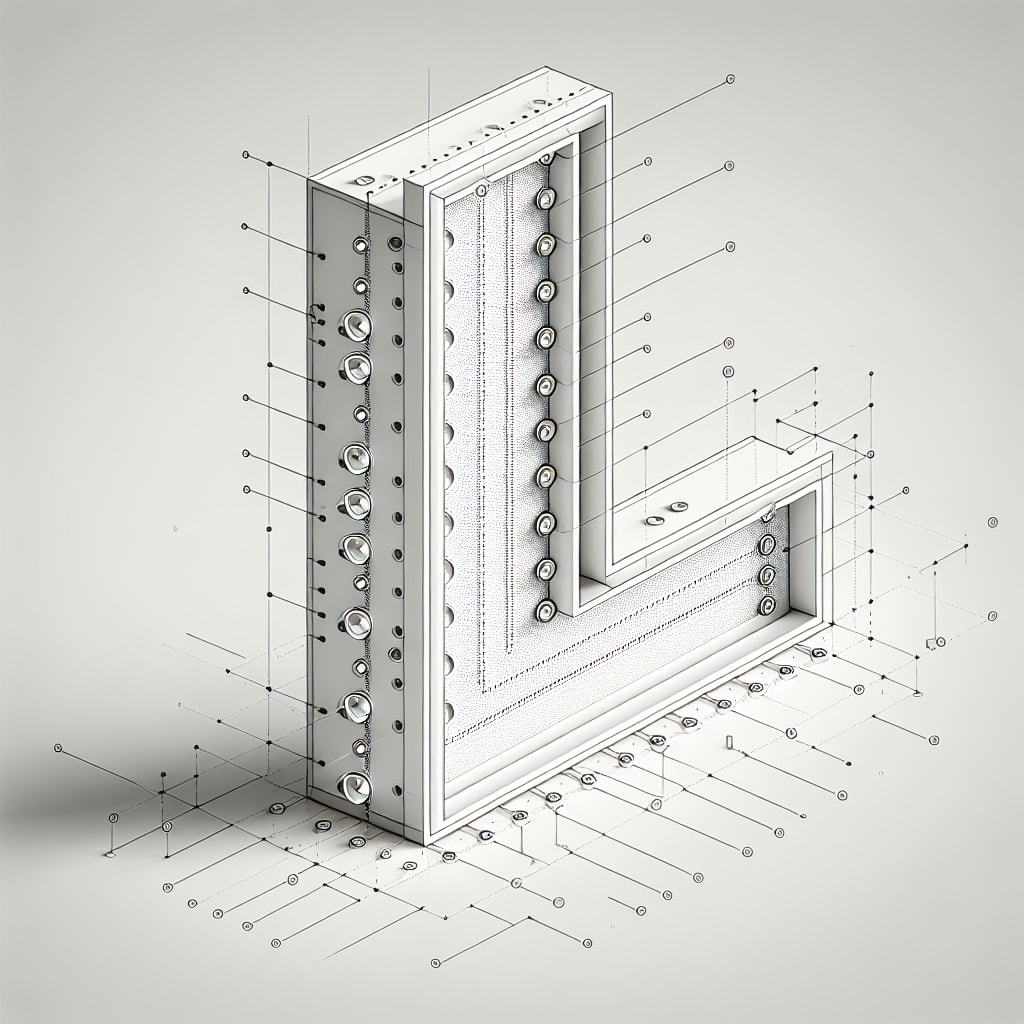
Getting LED module spacing right is one of the most visible parts of an illuminated-letter build. A poor layout can produce bright dots, bands, dim corners, color shifts, or letter-to-letter inconsistency. Adding more modules is not always the cure; it can increase hot spots, electrical load, and heat.
This guide is bounded production-planning information, not a wiring recipe or substitute for the selected LED manufacturer’s instructions, a listed sign system, approved drawings, or qualified electrical work. LA Prime Signs does not perform electrical work, field surveys, site measurements, permits, installation, or on-site service. Availability of any illuminated component must be confirmed in the written production scope.
Why does LED module spacing matter?
The spacing between LED modules determines how light mixes inside the channel letter before it hits the translucent face. Too little mixing distance creates visible bright spots directly over each module. Too much distance leaves dark areas between them.
Sign Builder Illustrated’s discussion of internal illumination makes the same central point: depth, stroke, face material, and module optics interact. The layout documentation for the exact product remains the better starting reference.
How should depth guide LED spacing?
Depth controls mixing distance, but it cannot supply a spacing answer by itself. A qualified fabricator’s documented development process should account for:
- The usable cavity: the actual module mounting plane to the production face, including raceways, backs, trim, clips, and fasteners.
- The exact module: beam pattern, output, input voltage, load, environmental rating, and approved mounting orientation.
- The manufacturer layout guide: documented row and center spacing for the intended depth and stroke range.
- Difficult shapes: narrow strokes, counters, corners, rounded terminals, and broad fields that may need different patterns within one letter set.
- A representative mockup: the widest and narrowest conditions at full depth with the actual face and overlays.
A depth-only table quietly assumes a particular beam angle, output, face transmission, and stroke. Change any of those and the table may no longer predict the result.
How does face material affect LED spacing?
The face is part of the optical system, not just a colored lid. Compare the complete production stack:
- White sign acrylic: Often diffuses well, but grade, thickness, and diffuser chemistry still matter.
- Colored acrylic: Saturated colors can transmit less light or shift appearance; do not assume closer spacing alone fixes it.
- Polycarbonate: Use documented sign-face grades and their transmission data rather than treating all sheet as equivalent.
- Vinyl, print, or paint overlays: These can change transmission and color, so include them in the test face.
If a face is too dark, adding LEDs can add heat and power without producing acceptable color or uniformity. A different LED spectrum, face formulation, cabinet depth, or sign type may be the better design move. Opaque backers such as Dibond panels have a different role and should not be assigned translucent-face assumptions.
What about shallow channel letters?
Shallow letters present a particular challenge because there is less distance for light to blend. Conventional modules may show through even when their center spacing looks reasonable on paper.
Purpose-built shallow-letter modules, broader optical patterns, diffuser films, or a revised depth can help. Compare options using the manufacturer’s documented test conditions:
- Beam pattern: A broad or batwing optic may move light laterally, but named beam angles do not guarantee a particular row spacing.
- Module profile: A smaller package can improve placement in tight strokes while changing output and heat density.
- Face and diffuser: Additional diffusion may improve uniformity while reducing transmitted brightness or altering color.
- Minimum stroke: Confirm that the module, connectors, bend radius, and adhesive footprint physically fit and remain serviceable.
How do multi-stroke letters affect spacing?
Wide strokes may need multiple rows, but “multi-stroke” does not automatically mean a single tighter center-to-center dimension. Row spacing, edge offset, module orientation, and cross-lighting all affect the result.
Narrow strokes receive more contribution from nearby reflective returns; broad fields behave more like a small cabinet. Map each cavity and preserve consistent edge conditions instead of forcing one repeated grid through every letter.
What are the power supply considerations?
After the optical layout is established, the qualified electrical/sign professional must design and approve the electrical system from exact component data. The production record should identify module count, documented load, input voltage, maximum modules per run, planned wiring segments, approved supply assignment, and component ambient limits without inventing a generic field-wiring detail.
- Connected load: Multiply the module’s documented load by the count and include other connected components.
- Supply sizing: Apply the power-supply and LED manufacturer’s required loading margin or temperature derating; do not invent one blanket percentage.
- Voltage drop: Long secondary runs and undersized conductors can create dim letters or uneven output.
- Environment: Match enclosures, wet-location suitability, ventilation, and temperature ratings to the actual mounting location.
- Compatibility: Use components intended to work together within the sign’s listing, approved design, and installation instructions.
Wired4Signs’ quoting guide is a useful example of the inputs suppliers consider. Treat supplier articles as planning aids; the selected product data, approved sign design, and applicable electrical requirements control the build.
What verified field inputs affect production?
The customer, installer, and electrical professionals provide the approved site information that affects enclosure and component planning:
- Ambient light and viewing angle: Evaluate readability by day and uniformity at night without assuming “brighter” is always better.
- Distance and mounting height: These influence letter size and perceived uniformity as well as output.
- Interior or exterior exposure: Match components and enclosures to water, dust, temperature, and access conditions.
- Return and back color: Reflective interiors usually aid distribution; test any nonwhite finish.
- Approvals: The customer resolves landlord criteria, sign and electrical permits, inspections, code compliance, and brightness rules for the site and jurisdiction.
Los Angeles and Southern California are not one exposure zone. Marine-influenced locations can put more emphasis on corrosion-resistant enclosures, connectors, fasteners, drainage, and seals. Sun-exposed or heat-retaining cabinets may need closer review of driver and module temperature ratings. Those conditions affect reliability and enclosure design; they do not justify changing module spacing without optical testing.
What should a production and electrical handoff document?
A controlled record helps the customer’s qualified installer and electrician understand the approved assembly without transferring field responsibility to the production shop:
- Document the layout: Save module model, batch-relevant color information, spacing, row offsets, wiring segments, and supply assignments.
- Test before final assembly: Use the production face at full depth and inspect representative letters for hot spots, dark areas, and color inconsistency.
- Check heat and voltage: Confirm operation remains within component limits and measure voltage at meaningful points on long runs.
- Plan maintenance access: Keep connectors, supplies, drain paths, fasteners, and removable faces serviceable.
- Preserve approvals: Module, supply, wiring-method, or enclosure substitutions require review against the listed or approved design.
A retrofit also requires the customer’s qualified professionals to assess the existing cabinet, wiring, disconnect, grounding or bonding, moisture intrusion, structure, and approvals. The installation-ready production and handoff guide explains the boundary between shop preparation and field work.
Need production planning for a storefront sign?
Good LED spacing comes from combining optical layout, electrical design, enclosure conditions, and service access. The arithmetic is useful, but the representative light test is what reveals whether the full assembly works.
Review storefront sign production, then request a production quote with approved artwork, customer-verified final dimensions, quantity, face and finish requirements, and installer- and electrician-approved specifications. Any illuminated-component scope must be confirmed in writing. Site verification, electrical design or connection, mounting, engineering, permits, code compliance, access, and installation remain with the customer and qualified professionals.
FAQ
What is the standard LED module spacing for channel letters?
There is no standard dimension that is safe to reuse across every build. Start with the layout table for the exact module, depth, face, and stroke range, then verify the result in a representative full-depth sample.
How does face material affect LED spacing in channel letters?
Face transmission, color, thickness, diffuser behavior, and graphics all affect how light blends and how much output reaches the viewer. White sign acrylic is often forgiving, while saturated colors or printed films may require a different module, density, or depth. Test the actual production stack.
Why do my channel letters have hot spots?
Hot spots can result when the face is too close to the LEDs, output is too concentrated, spacing does not suit the letter shape, or the face and interior do not diffuse light as expected. Diagnose the whole build before adding or removing modules.
What LED modules work best for shallow channel letters?
Use modules whose manufacturer documents performance at the planned shallow depth and stroke width. A wide beam or purpose-built shallow-letter product may help, but its spacing, face compatibility, thermal limits, and power requirements still need to be followed and tested.
Who should connect an illuminated sign to building power?
The customer must use the qualified and licensed trades required for the site and jurisdiction. Field wiring, disconnects, grounding or bonding, branch-circuit connections, permits, and inspections are not LA Prime Signs production services.