
CNC Router Bit Selection for Dimensional Sign Work
The bit, material, collet, spindle, hold-down, dust or chip control, and toolpath operate as one system. Select them together, test safely, and use manufacturer data instead of copying a stranger’s feeds and speeds.
Key takeaways
- Start with the exact material, thickness, visible edge, smallest detail, and finish requirement—not the bit already in the spindle.
- Bit geometry, flute count, diameter, stick-out, chip load, pass strategy, and evacuation all affect heat and edge quality.
- Acrylic, PVC, ACM, HDU, and wood behave differently; begin within the machine, tool, and material manufacturers’ limits.
- A controlled scrap test can reveal melting, chatter, tear-out, delamination, poor hold-down, and tool deflection before the production sheet is at risk.
- CNC work requires trained operation, secure workholding, suitable guarding and extraction, and material-specific safety controls.
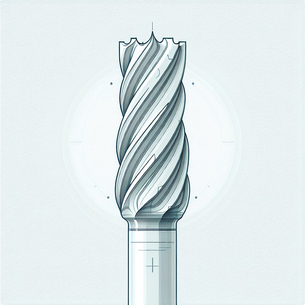
A router bit can cut the correct outline and still leave the wrong part. Melted acrylic, fuzzy HDU, torn wood grain, lifted aluminum-composite skins, chatter, and oversized inside corners all begin with mismatched tooling or process assumptions.
For dimensional sign components, define the finished edge before selecting the tool. A concealed roughing cut, a paint-ready return, a clear polished-looking acrylic edge, and a carved face do not call for the same bit or toolpath.
Why does router-bit choice matter for dimensional letters?
Bit geometry controls how the cutter enters the material, forms and clears chips, loads the top and bottom faces, and resolves small details. Diameter also establishes the smallest inside radius the tool can produce. A file with sharp internal corners may need design relief, a smaller finishing tool, or another process.
Tooling is only one part of the result. Spindle speed, feed, depth per pass, radial engagement, machine rigidity, runout, collet condition, stick-out, hold-down, and extraction change the load on the same bit. Use the machine and tooling manufacturers' data as the starting envelope, then validate on scrap from the actual batch.
Which router-bit types are useful for sign components?
A small tool library can cover many sign operations, but no category is automatically suitable for every substrate. Check the cutting-tool maker's current material chart and dimensional limits before use; a general tooling overview is not a replacement for the tool, machine, and material instructions.
End mills for profiles and pockets
Flat-end tools are common for profiles, pockets, and vertical walls. Single-flute or O-flute geometries are often considered for thermoplastics because chip evacuation and heat control are critical; upcut, downcut, and other geometries load sheet faces and hold-down differently. Select the exact tool for the substrate and whether the top edge, bottom edge, or both remain visible.
- Confirm that flute length covers the programmed cutting depth without rubbing the shank.
- Use the largest diameter that can resolve the required detail while respecting spindle, collet, and machine limits.
- Plan roughing and finishing passes when one aggressive profile pass cannot meet the edge standard safely.
Ball-nose bits for contoured surfaces
Ball-nose tools are suited to 3D reliefs, rounded grooves, and curved surfaces. Surface finish depends on ball diameter, step-over, toolpath direction, material behavior, and the amount of stock left for finishing. A small step-over may improve scallop height but increases run time and does not correct chatter or a dull tool.
- Use a separate roughing toolpath when the finishing tool should remove only a controlled allowance.
- Preview boundary behavior so the tool does not roll over an edge that should remain crisp.
- Approve the intended texture; some routed reliefs are designed to show tool character, while others are not.
V-bits for engraving and chamfers
V-bits can engrave lines, create chamfers, and produce variable-width V-carved lettering. Their apparent width changes with depth, so material flatness, spoilboard condition, hold-down, and surface mapping can matter greatly. Verify the included angle and tip geometry rather than treating every “90-degree” tool as identical.
Compression bits for clean panel faces
Compression geometry combines opposing cutting directions to protect both faces when the sheet and pass depth suit the tool. If the first pass does not engage the intended portions of the flute, the expected face quality may not appear. These tools are commonly considered for wood products and laminates, but suitability for a particular sign panel must come from the tooling and panel guidance.
How should tooling change for wood and HDU?
Material name is only the beginning. Density, grain, coatings, skins, recycled content, temperature, storage, and batch variation can change the cut. Keep a verified job record that names the material and tool rather than labeling a setting merely “plastic” or “wood.”
HDU (high-density urethane)
HDU is often routed for dimensional letters and carved panels because it has no wood grain, but density and manufacturer guidance still matter. It creates fine dust and can show fuzzing, tool marks, fragile detail, or chipped coatings when the process is wrong.
- Choose geometry recommended for the exact density and operation.
- Test small strokes and raised details before routing the complete sign.
- Use collection and housekeeping controls designed for the dust; consult the material safety data sheet.
Wood and wood products
Solid wood adds grain direction, moisture, knots, and movement. Plywood, MDF, and laminated panels introduce glues, layers, and different dust hazards. General routing concepts can orient a new operator, but production settings and safety controls must match the exact stock, tool, and machine documentation.
- Orient visible faces and grain before nesting the file.
- Test climb or conventional finishing direction through the approved machine process rather than assuming one direction always prevents tear-out.
- Account for paint or clear-finish preparation when setting the edge-quality target.
Which specifications and process variables need review?
Once the tool family is chosen, verify the complete setup:
- Diameter and corner radius: control detail resolution, rigidity, and internal geometry.
- Shank and collet: must match exactly and remain within tool and spindle limits; inspect wear and cleanliness.
- Cutting and overall length: use only the reach needed, with safe clearance and minimal unsupported stick-out.
- Flute geometry and count: affect chip space, face loading, and achievable chip load for the material.
- Tool material and coating: choose from manufacturer recommendations; a coating useful in one substrate may add heat or adhesion in another.
- Feed, speed, engagement, and pass depth: calculate and test them as a related set within every component's rating.
- Hold-down and extraction: must keep the part stable while removing chips or dust without pulling small pieces loose.
Record the material product, thickness, tool part number, measured diameter if relevant, machine, collet, toolpath, settings, hold-down, result, and tool life. A reproducible record is safer than a “magic number” detached from its setup.
How should router bits be inspected and maintained?
Dull or contaminated tools raise heat and cutting forces. Follow the tool maker's inspection, cleaning, sharpening, storage, and retirement guidance. Do not scrape carbide with another hard edge or soak a tool in an unapproved chemical.
- Inspect cutting edges for chips, buildup, wear, and damage before installation.
- Inspect the collet, nut, holder, and spindle interface; tool replacement will not correct excessive runout or a damaged collet.
- Store cutting edges so they cannot strike one another, and identify tools whose size changes after sharpening.
Do Southern California site conditions change the bit choice?
The installation climate does not create a universal CNC setting. It changes the material and finish specification first. Coastal salt and moisture may steer an exterior project toward one substrate, coating, hardware, or edge-sealing system; inland heat and UV may steer it toward another. The router process must then be validated for the selected material.
Shop temperature and material conditioning can also affect plastics and wood, but the acceptable range comes from the material and tooling suppliers. Do not use a “coastal” feed rate or assume every Southern California project needs the same substrate.
The customer and qualified installer must supply final field dimensions, verified site conditions, mounting design, structural requirements, code criteria, and installation specifications. LA Prime Signs uses approved production inputs to route, finish, and prepare components; it does not conduct site surveys, field measurements, access planning, or installation.
What safety checks belong before a cut?
- Use trained operators and follow the CNC, spindle, collet, tool, hold-down, and material instructions.
- Verify that guards or enclosure, extraction, fire controls, and PPE are suitable for the exact dust, chips, coatings, and substrate.
- Keep people clear during operation; never reach into a moving machine or rely on software preview as the only clearance check.
- Use the required energy-control procedure before tool changes, clearing jams, or maintenance.
- Prove new files and setups through the shop's controlled process, with safe clearances and a scrap test before production.
Bottom line
Router-bit selection is finish planning plus process control. The correct tool is the one approved for the exact material, capable of the required geometry, compatible with the machine and extraction system, and proven by a controlled test.
If you are specifying routed dimensional letters or panels, request a production quote with approved artwork, customer-verified finished dimensions, material preference, visible-edge requirements, quantity, finish, and installer-approved handoff details. Current CNC capability, tooling, substrate availability, and safe production scope must be confirmed before a method is promised.